COMPONENTS
This page provides a detailed overview of the hardware components used in the project. Each component is listed with a brief description, an explanation of why it was chosen, and possible alternatives that were considered during the design phase.
The goal was to select low-cost, effective, and easily available components in order to keep the overall project cost minimal and accessible.
Components list:
- Arduino Nano
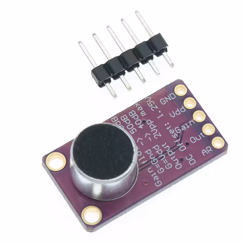
- Microphone (MAX9814)
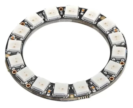
- LED ring (16 LEDs, WS2812b)
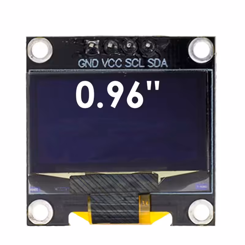
- OLED display (0.96 inches, monochrome, SSD1306)
- Passive speaker
- Push button
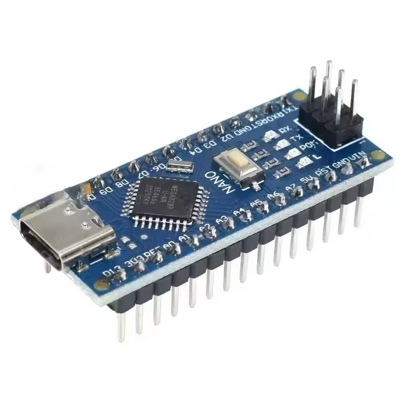
Arduino Nano
The Arduino Nano was chosen as the core of the project due to its low cost, compact size, and sufficient processing power for the required FFT calculations and real-time LED control. Additionally, I already had good familiarity with the platform, which allowed for faster development and debugging.
To further reduce costs, I opted for a non-official board. Upon arrival, I discovered it was equipped with an ATmega328PB chip instead of the standard ATmega328P. This caused incompatibility with the official bootloader so I had to install and flash the board using the MiniCore package by MCUdude (GitHub), which offers full support for the PB variant.
An ESP32 was also considered as an alternative, thanks to its higher performance and floating-point support. Despite its capabilities, this board is almost twice as expensive, has higher power consumption, and its built-in Wi-Fi and Bluetooth features were not needed for this project.
Price: $3.50 (*)
LED ring
I choose a 16-LED RGB ring based on the WS2812B addressable LEDs. This was one of the pre-assembled options available for purchase, and its size matched perfectly with the screen, like in my concept!
The main concern was power consumption, as Arduino can provide a maximum of 1A on the 5V line.
The
datasheet indicates a maximum of ~60mA per LED when fully lit in white at full brightness.
For this project I considered:
- brightness set to <50%
- only half of the LEDs (8) lit at the same time
Given these conditions, the power draw remains well within safe limits.
An alternative option would have been to use individual monochrome LEDs, but this would have
required manually building the circular layout and additional components (i.e. current-limiting
resistors).
Also, multiple digital pins are needed to control each LED (one pin per LED); instead, when using an
addressable
LED ring, you can use a single digital pin, greatly simplifying both wiring and code.
Price: $3.00 (*)
Display
I selected a monochrome white OLED display under 1 inch primarily because of
its compact size, which allowed it to fit inside the LED ring — a key part of the device’s design.
It was intended to display current tuning note and provide basic user interface (e.g. menu navigation -
not implemented).
Its low power consumption, high contrast, and sufficient resolution made it ideal for showing characters
and simple information.
It is based on the SSD1306 driver and the main challenge was memory usage: using the full Adafruit GFX + SSD1306 graphics library take up much of the Arduino Nano's limited flash and RAM, leaving insufficient space for the FFT processing. To solve this, I switched to a minimal ASCII-only library, which provided basic character output with a much smaller memory footprint.
Price: $2.20 (*)
Microphone
For audio input, I chose the MAX9814 microphone module, which includes automatic gain control (AGC). My initial plan was to use a smaller MAX4466 module with fixed gain, but during testing, it became clear that it struggles to capture the guitar signal reliably — especially after the first few seconds, as the sound quickly fades in volume.
Switching to the MAX9814 with AGC significantly improved the sustain and clarity of the detected signal, making frequency analysis more stable and extended over time.
However, this also introduced some drawbacks: background noise and unwanted sounds resulted amplified, affecting the accuracy of pitch detection. To mitigate this, I implemented software filtering such as putting an amplitude threshold to ignore weak or noisy signals and a frequency debounce mechanism to ensure stable note detection (more details in software section).
Price: $2.50 (*)
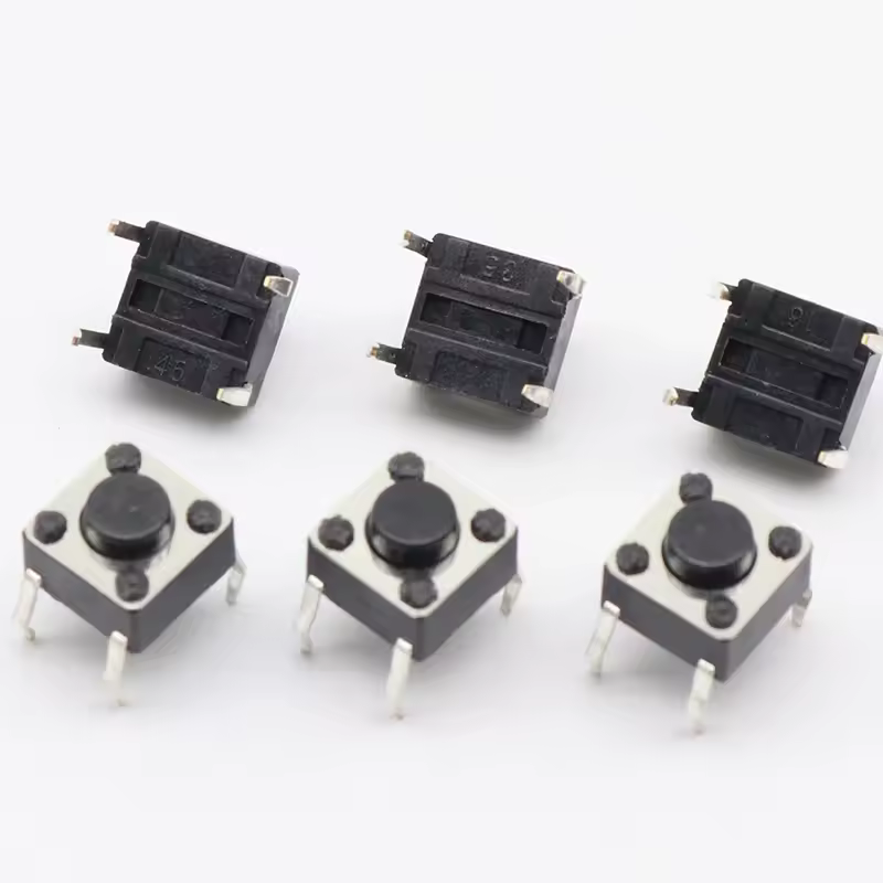
Push button
A push button was used to allow basic user interaction with the device.
Initially, the design included two buttons to navigate potential menus, but after simplifying the
interface and removing menu functionality, a single button became sufficient.
Its behavior is straightforward:
- short press: cycle through the six guitar strings
- long press: play the reference tone for the selected string
This minimal setup reduced hardware complexity while still enabling all necessary interactions.
Price: $0.05 (*)
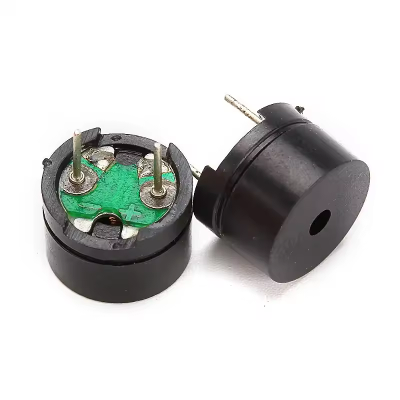
Passive speaker
For generating the reference pitch sound, I used a basic passive buzzer.
A higher-quality speaker wasn't considered necessary, since the ear-tuning step doesn’t require high
audio fidelity and a better speaker would have introduced power handling concerns.
The actual precise tuning is handled by the tuner itself, so, although the buzzer produces a rough, buzzing tone, it is adequate for prototyping purposes and serves its role of giving the user a coarse audio reference for each string.
Price: $0.20 (*)
SCHEMATICS
Here you can find the schematic diagram and breadboard layout used for the project.
While the circuit is relatively simple, I recommended you to refer to each component’s
datasheet for correct wiring and usage guidelines.
If you're not already familiar with a component, it's a good idea to test it individually first, using simple example sketches, before integrating it into the full circuit. This will make debugging much easier and help you better understand how each part works.
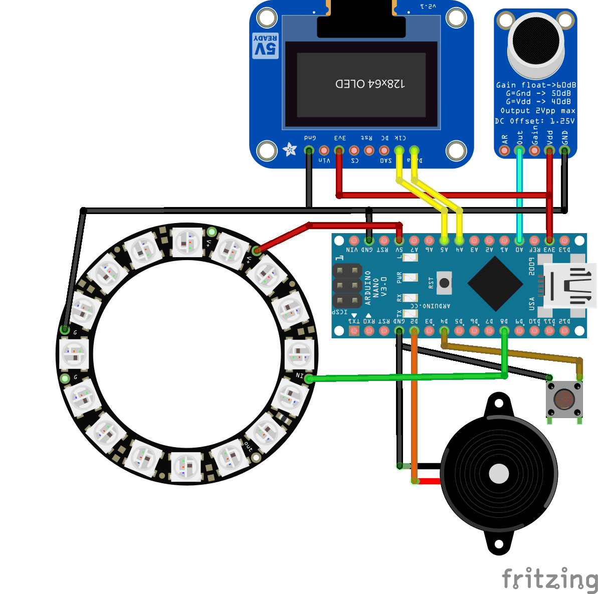
Figure 1: circuit layout.
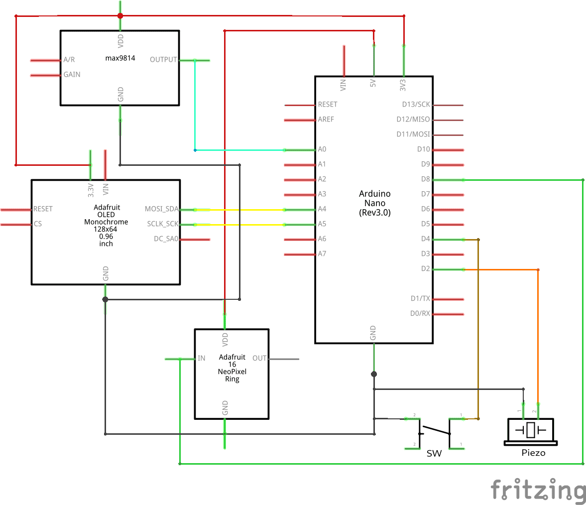
Figure 2: circuit diagram.
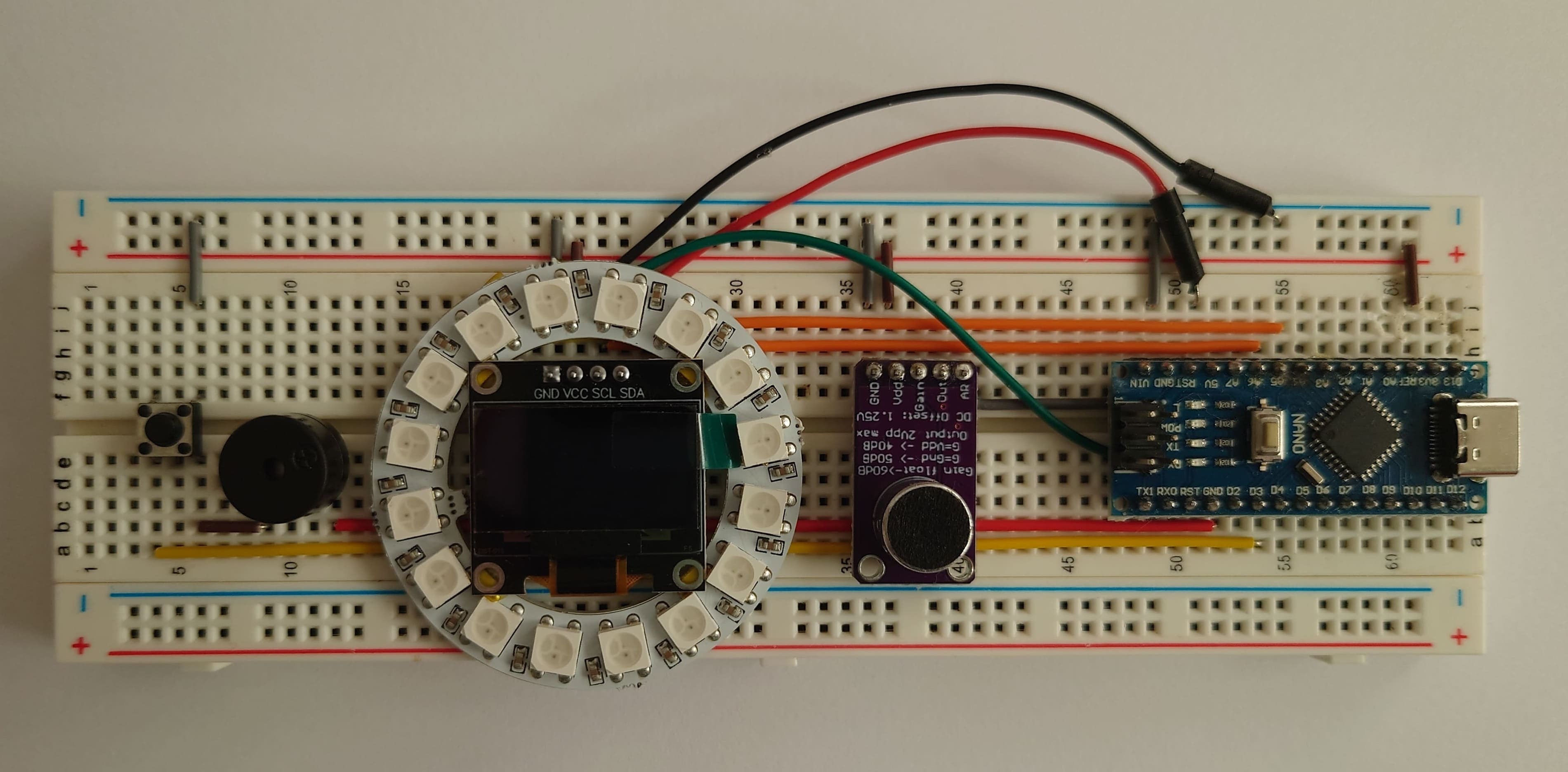
Figure 3: top of the breadboard.
(*) Prices current as of April 2025 by chinese resellers.